Building the Better Battery Switch
Kill or Be Killed
Almost every motorsport body requires some form of an electrical isolation (kill) switch. The requirements between sanctioning groups vary, but typically are worded such that in the event of an emergency, track workers can safely stop the operation of the vehicle engine
Not all kill switches are created equal and not all kill switch wiring is created equal.
Safety should be available to everyone and being a motorsport hobbyist is expensive enough as it is. With some foresight and planning, one little circuit board with some help from proven, robust components, can do the same thing as much more expensive systems.

Existing Solutions
Before going down the path of designing something “new”, the various existing solutions were reviewed. Each had their pros and cons based on the complexity and price of the product.
- Two-Pole mechanical switches
- These are the switches everyone’s familiar with. Big chunky switches with two terminals to attach battery cables
- Have been around the longest but are also the simplest and provide no additional features
- Can be remotely actuated via cable; usually only one external kill switch access point
- Typical use case requires the switch to be rated for the continuous and instantaneous load demand expected
- Large battery cables required to be routed directly to it, in proximity to the driver and adding length to the load path
- “4430” style switches
- The “4430 style” switch that motorsport outlets sell is probably the most widely used
- Upgraded version of two-pole switch that adds alternator load-dump protection, and ignition system control
- Same limitations in actuation points, load rating, and cable routing
- Basic electronic contactors
- Kits that use a heavy-duty continuous rated contactor as the isolation device
- Relatively easy to source the parts
- Uses an electronic switch for actuation which also allows for multiple kill access points
- Isolation device (contactor or HD relay) can be remotely mounted in-line with the battery cable, reducing overall load path
- typically lack alternator load-dump protection or ignition output control without extra circuits
- Advanced electronic switches
- Aftermarket companies offer a complete all-in-one solution. Some “electronic” options are function limited, others are feature rich.
- For example, the Cartek “GT” model provides a power feed to the ECU or ignition system and also isolates the battery on actuation. Both the GT and XR models can sequence the alternator and ECU during shut-down
- Usually small and light weight
- Usually ground-path switching, not high-side switching
- Not easily replaceable with off-the-shelf parts
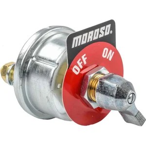
Two pole kill switches are about as simple as they come
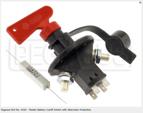
Pegasus P/N 4430 is a staple among enthusiast builds
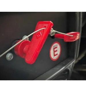
Some switches can be remotely actuated by cable
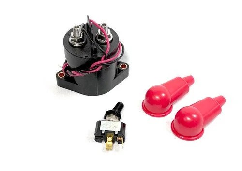
Kits use a continuous-duty relay but lack alternator load-dump protection
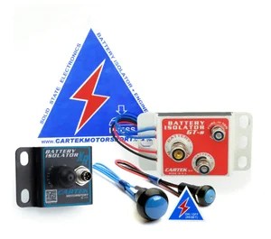
Aftermarket electrical kill switches offer additional functions
Building a Better Middle Ground
The idea was to re-packaging and borrow some of the best features from each of the options above into a single module. Make it easy to service, find parts, and improvise a replacement for track-side repairs.
Using HD starter solenoids or motor contactor as an isolator is typical; after all, these devices are designed for repeated high-current make/break cycles. Years in manufacturing means they’ve also been designed to a price point and they’re widely available. There’s no need in trying to fix something that’s not broken. Using a contactor alone however does not provide load-dump protection, an auxiliary output to control ignition systems, or alternator field exciter “cut off”.
Enter designing a controller, the battery isolator module. A simple single-pull, dual-throw relay handles the low-current switching. Including fuses and a resistor pulls everything together. At its core, the battery isolator module is just controlling the isolation device (DC contactor) while also providing the extra features like battery load dump protection and multiple access points for a kill switch.
Design Requirements
With the idea conceptualized, there were some key design points that needed to be considered for the final product
- Simple and Robust
- This is a safety system. The solution needs to be robust, reliable, and provide repeatable performance.
- Failed safe
- Sometimes life happens. There’s a big difference between “ideal conditions” and an actual accident. The solution needs to fail to a safe state.
- Flexible
- Limiting to a single point of access or single isolation means should be avoided if possible.
- Cost effective
- Motorsports are already expensive enough. Usually the good stuff is “buy once cry once” but keeping more money for tires is great too!
- Easy to service or source spares
- Using exotic, hard to source, or parts without pin-wise alternatives should be avoided. Replacement parts should be easy to produce from multiple sources.
- Easy to integrate to existing systems
- Requiring extensive changes to existing motorsport wiring solutions or OEM wiring should be avoided. Implementing this device should be as simple as possible.
Just that simple
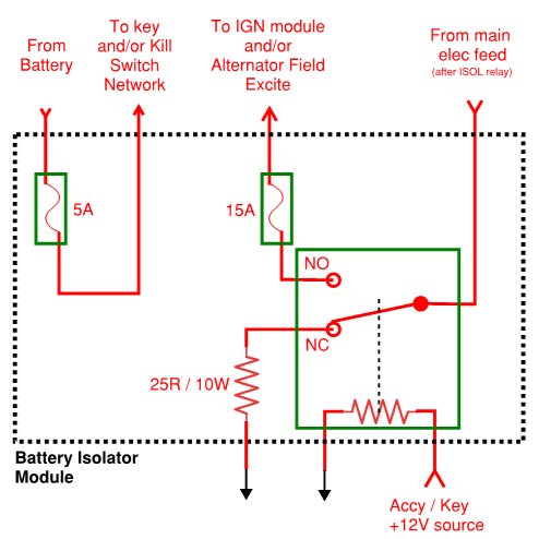
Both the design and the implementation of the battery isolator was kept as simple as possible. Extra features like current monitoring, sequenced shutdowns, and fault indication are nice but add complexity.
If something goes wrong at a racetrack, it’ll typically need a “field repair”. The alternative of keeping spares gets more expensive the fancier the module gets. Keeping the design and individual components simple and independent to one another means that stocking spares doesn’t require a stock portfolio.
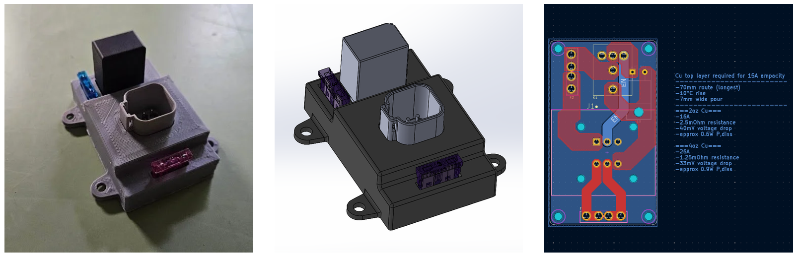
Two fuses and a mini relay are all that’s in the module itself. Packaged nicely into a single PCB with it’s own Deutsch connector means a compact footprint with no extra wires.
All that’s needed in addition to the battery isolator module is a continuous-duty rated contactor (or heavy duty relay) and the switch(es) of choice.
Easy to Implement
Each car is a little different, so the module must work with multiple alternator types, engine control strategies, and electrical distribution systems. The battery isolator module does three things:
- Control isolation of the battery feed
- Provide an additional auxiliary power feed to the ECU/Ignition
- Protect the system from shutdown voltage spikes
Using a HD contactor means the isolation device can be placed inline with existing battery wiring. It can be activated by one or more kill switch, placed wherever and however the builder sees fit. After the shut-down matters too, additional connections provide auxiliary power output and shutdown load shunting.
The battery isolator module integrates neatly with any system and works with common “1 wire” and “3 wire” alternators. The electrical distribution downstream of the isolator does not matter and can be a factory fuse block or custom PDM.
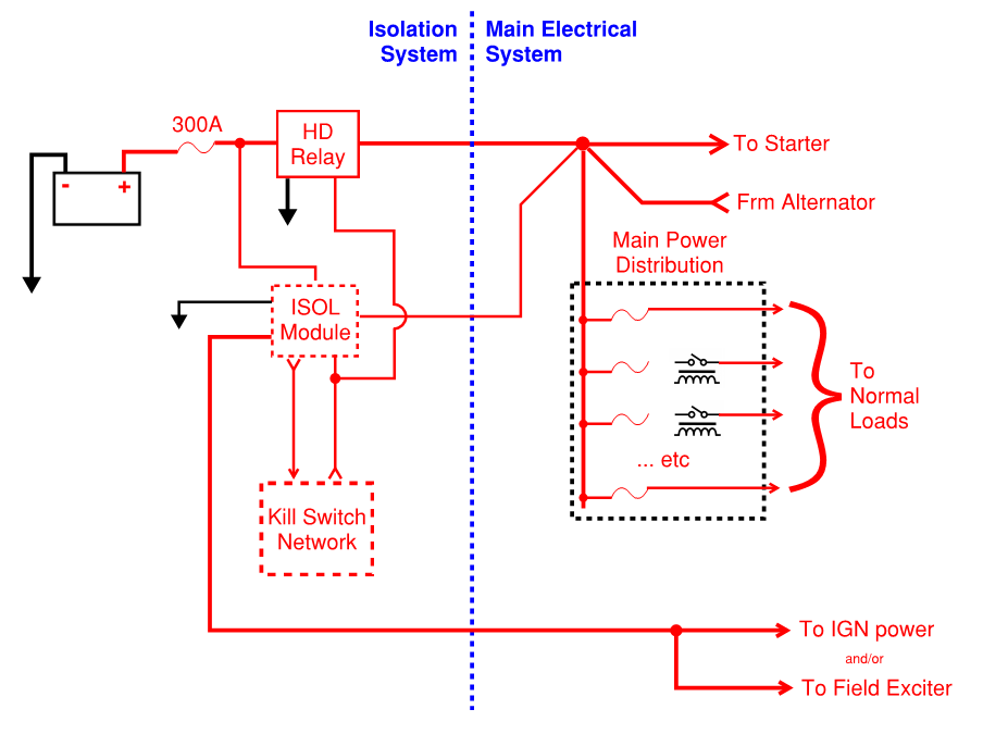
In-Depth Protection
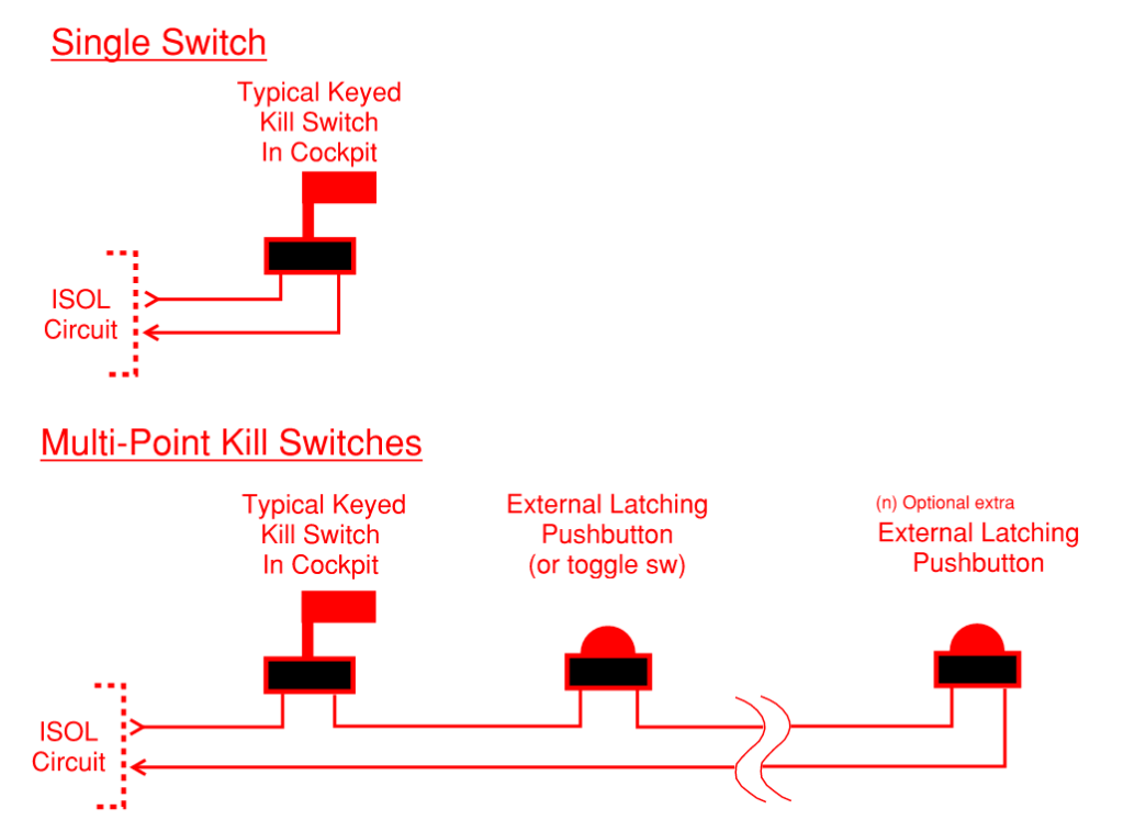
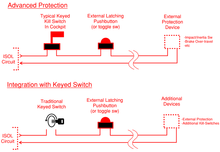
Standard kill switches only allow for manual activation. If the switch isn’t flipped, the battery isn’t isolated. Adding a dedicated “trigger network” or “isolation network” allows for in-depth protection in a variety of situations.
The isolation network for the battery isolator module includes its own fused output and is normally energized, de-energize to isolate. This means that in the event of a cut wire or blown fuse, the battery is automatically isolated.
The use of a series “isolation network” also means that a variety of switches or triggers can be used as triggers including:
- Standard twist-type “flag key” switches
- Push-off, twist-on kill switches
- Toggling push-button or normal toggle switches
- Inertia or Impact switches
- Brake over-travel switches
- OEM key switches
More than minimum
The battery isolator module helps to do more than just cut the feed from the battery. Through the 6-pin Deutch connector on the board, it also provides a fused auxiliary power output that de-energizes on shut-down and also protects the downstream bus from voltage spikes.
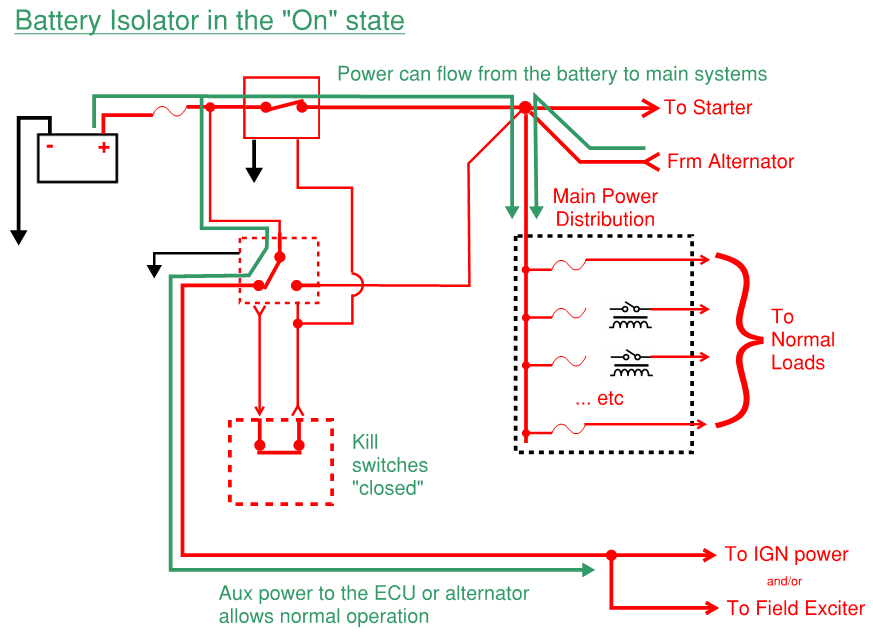
All kill switches wired into the battery isolator module must be closed in order for it to be in the “on” state. When “on”, the module sends power to the isolation relay connecting the battery to the main bus. It also provides a fused feed that can supply power to the ECU, ignition system, or alternator field winding.
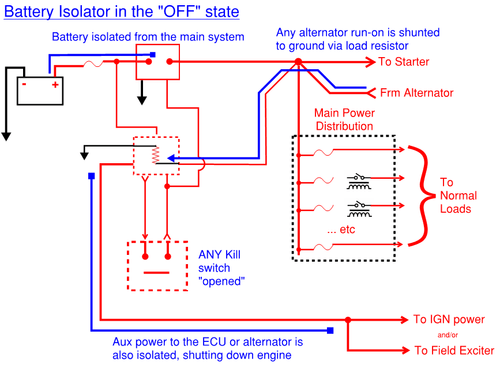
If ANY kill switch connected to the battery isolator module is opened, it enters the “off” state. When “off”, the module:
- removes power from the isolation relay, disconnecting the battery from the main bus.
- Auxiliary power is isolated, providing an “off” signal or removing power from devices
- The bus downstream of the isolator is connected to a load-dump relay, to prevent damage due to over-voltage from alternator run-on
High side switching
One thing the battery isolation module system shares with a simple switch is ability to switch the high-side or positive (+) voltage from the battery. Under ideal circumstances, isolating either the ground or power from the battery can provide the same effect, with some caveats. High side switching specifically circumvents two key issues:
- Ground (-) side switching can potentially miss alternate ground paths, resulting in incorrect operation.
- As an example, an alternator is typically grounded to the engine through its case; depending on where the alternator is connected to the main system, simply cutting the battery feed may not stop the motor.
- During an accident, the ground-return path can easily be restored through a fault, bypassing a “ground break” style isolation device.
The unfortunate reality is that when a kill switch is needed the most, the surrounding car isn’t going to be in ideal conditions. Protection on the “high side” or positive side of the battery can be achieved through a high-amp, slow-blow fuse in combination with an isolation contactor like the battery isolator module system uses.
Multiple protection devices on the positive side of the battery placed as close to the battery as possible also help ensure that when a kill switch is activated, the “live wire” from the battery is as short as it possibly can be. This helps reduce the possibility of arcing and additional ignition hazard after the accident.
Lastly, it’s typically easier for people to visualize the flow of the “positive side” of the battery and how that travels to all devices. This may not be an issue for more experienced users but the goal here is to help EVERYONE successfully wire their system.
Early Attempts
Initially, a solid state system was considered. Putting together a proof of concept was relatively easy using off-the-shelf components. The concept was to use an array of standard P-channel MOSFETs to provide the switching capability of the switch. While the idea worked on paper, several known issues posed challenges:
- High R-ds,on
- P-channel MOSFETs traditionally have a higher “on” Drain-Source resistance. This means more power loss when the isolator is conducting and also means more heat
- For the proof of concept, the hope was that multiple MOSFETs in parallel would both provide additional robustness but also a lower “on” resistance
- Constant Power Required
- High-side switching a P-channel MOSFET also requires a “pull-up” resistor to keep the MOSFET in the “off” configuration. This could lead to eventual battery drain-down. Typically, the gate-current of MOSFETs is relatively low and would be less than most “always on” systems like a security system
- Additional considerations
- As FET technology continues to progress, some of the above concerns are mitigated. Relatively low R-ds, on and high P,diss FETs are more commonplace now than they were 10-15 years ago. Even still however, that performance comes at a price. Spending $35 per transistor at potentially x6 per board gets expensive in a hurry!
- Requiring the pull-up resistor to remain in the “isolated” state may result in inconsistent power-up behavior and also does not fully satisfy the “failed safe” configuration desired
A prototype was constructed to confirm the various considerations and performance goals.
Two 12-gauge strips of copper formed common busses that 6, TTO-220 form factor, Vishay MOSFETs were directly soldered to. These MOSFET were chosen due to their combination of relatively low R,ds-on (for a P-channel FET), high current capacity, and relatively low price.
This prototype was tested in an existing electrical system, with some additional provisions to provide alternator dump protection while isolating. Initial testing was positive, however during extended high-load (engine cranking periods of 10-15 seconds), a decrease in battery output was noted. This was likely due to the heat-up of the MOSFETs and increase of the R-ds,on during high load demand.
Due to the compromise in performance vs design goals, this design was not used but was still a valuable test as a proof of concept.
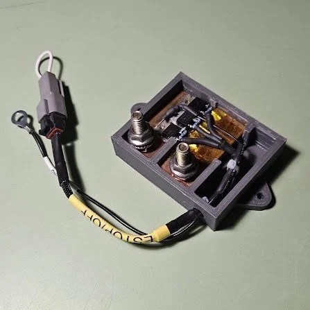
Design Verification
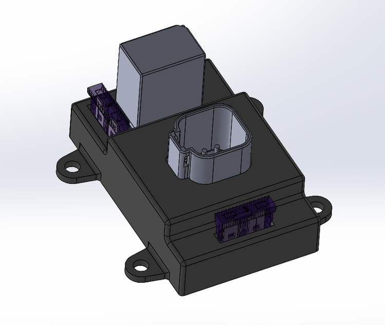
A non-PCB prototype using standard automotive relays and fuses has been in a track car for the last 4 years without issue. During those 4 years, the switches wired into the battery isolation circuit provided the sole means of cutting electrical power to the car. An additional ignition switch is present, however this was done on purpose to stress test the system in a less than ideal manner.
After designing the final battery isolation module and initial manufacture, the performance and reliability of the new module needs to be tested. The final steps of design verification include a test system to cycle the load isolation module through a high number of cycles in a short period of time.
A simple test setup was created to provide a cyclic make/break test platform to test durability and measure voltage response during operation of the battery load isolator.
- A “3 wire” style alternator connected to a battery.
- The connection is interrupted by a DC contactor controlled by the battery isolator module (similar to the diagrams shown above).
- An AC mains powered “driving motor” serves as the means to run the alternator.
- An external controller first triggers the isolation module and then ramps-down the “driving motor” to simulate an engine shutting down.
- Once stopped, the controller will re-connect the battery, start spilling the alternator, and wait until steady state is reached before repeating the cycle over again.
During the lifetime cycle testing, several metrics will be recorded and observed.
- The physical state of the load isolator module will be observed, noting any electrical stress or damage.
- A separate data logging module records the battery voltage and alternator voltage. The intent is to record the performance during shutdown and observe any voltage-spikes from alternator run-on or breaking the connection to the battery.
- Total number of cycles will be tracked, noting the cycles to failure or number of cycles achieved before the test ends
The final results of the test are yet to be compiled but will be recorded here on their completion.
